Predesigned Mechanisms and Components
Predesigned Mechanisms
A complete line of off-the-shelf components for assembling an unlimited variety of geared mechanisms. Gear ratios to 78,125:1, zero-backlash spring-loaded gears and torque-limiting slip clutches are featured. Assembled units meet design and materials requirements of MIL-E-5400 and MIL-E-16400.
*For complete data and catalog of stocked components, Request Bulletin 102.
Custom Designs
PMC specializes in design and manufacture servo mechanisms and mechanical modules to user requirements for airborne, ground support, communications, fire control and other critical applications. The units shown below are typical of the mechanisms designed and manufactured for military and industrial equipment
*Short lead time delivery on both prototypes and production quantities.
- Assemble an unlimited variety of servo and instrument mechanisms from stocked components in minutes.
- Deliver proved-out designs in prototype or production quantities with no expenditures for design and fabrication
- Assure successful engineering and production commitments by using identical units in the breadboard, prototype, and production phases.
- Meet the design and material standards set in MIL-E-5400
- Gear ratios from 1:1 to 78,125:1
- Accommodates all standard miniature synchros, motors, pots, and similar rotating shaft components.
- Zero backlash spring loaded gears and torque limiting slip clutches in all ratios.
- Fixed shaft center design assures uniform and reproducible results.
Enclosures, modifications and special designs in accordance with your requirements.
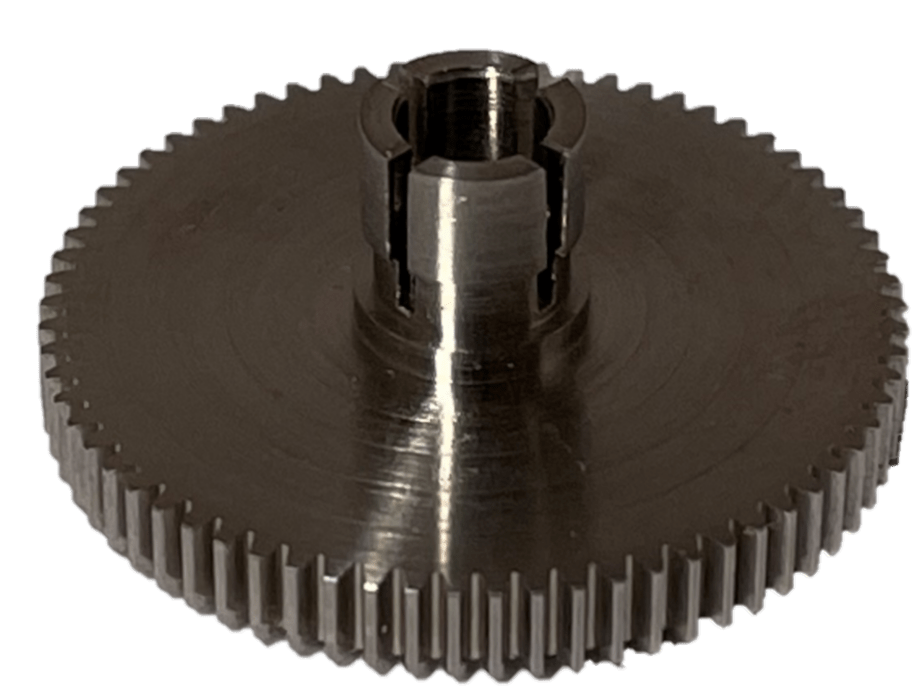
Gears: Part No. 2016
AGMA Precision 1 or better, 96 pitch, 20° pressure angle, 18-8 corrosion resistant steel. Size range, 22 to 110 teeth. Standard bores are .0900, .1200 and .1250. Bore tolerance is +.0003, -.0000. Pitch diameter tolerance +.0000, -.0010. Face width, “a” is .093 for 66 teeth and less, .062 for 67 teeth and more. When used with the .6975 centers of the PMC Gear Plate Assembly (Part No. 2036), a meshing pair must total 132 teeth.
When Ordering, Specify Part No. 2016 – Number of teeth and Bore.
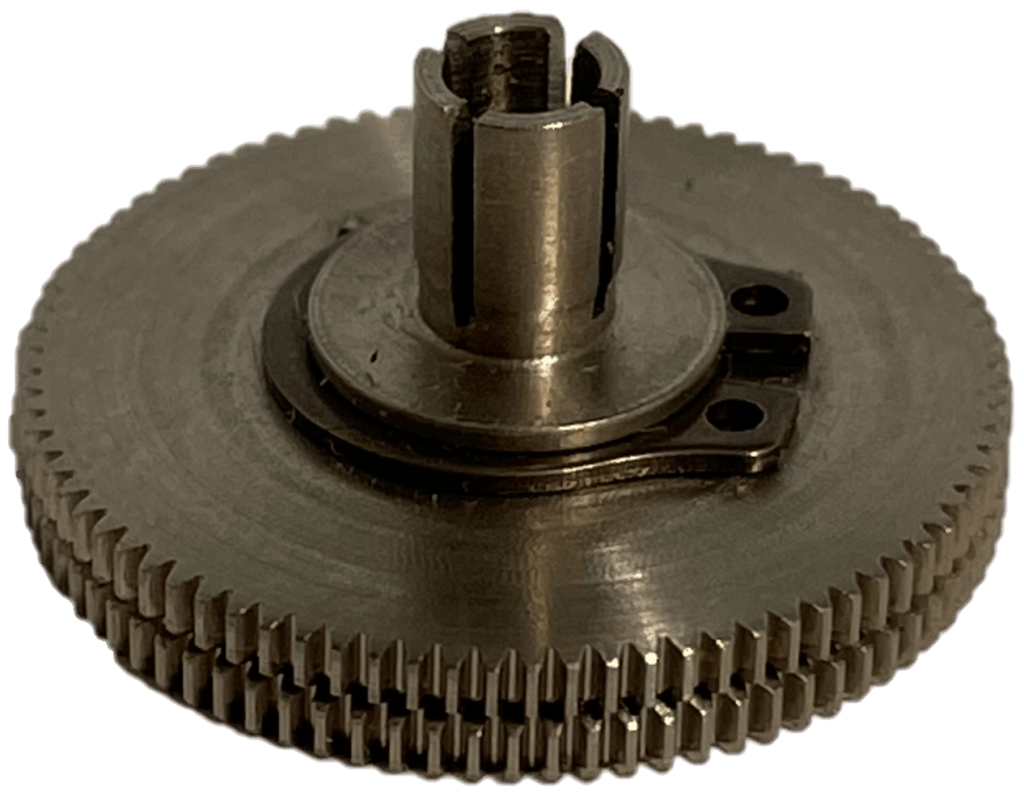
Antibacklash Gears:
Part No. 2030
Interchangeable with Part No. 2016 gears and of the same precision, tolerances and material. Size range, 66 to 110 teeth. Internal spring provides zero backlash.
In conjunction with Part No. 2016 pinions, they provide the Gear Plate Assembly (Part No. 2036) with backlash free gearing in all 45 ratios from 1:1 to 5:1. For ordering purposes, preferred sizes are 66,88,00 and 110 teeth.
When Ordering, Specify Part No. 2030 – Number of teeth and Bore.
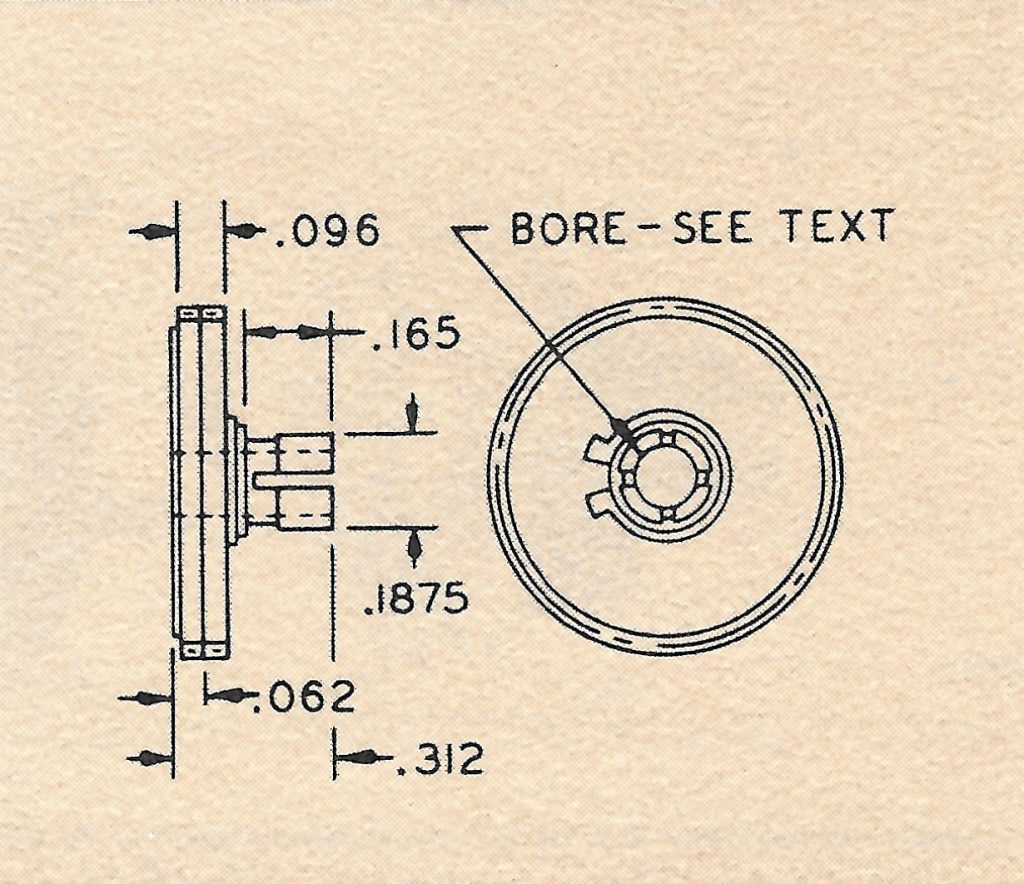
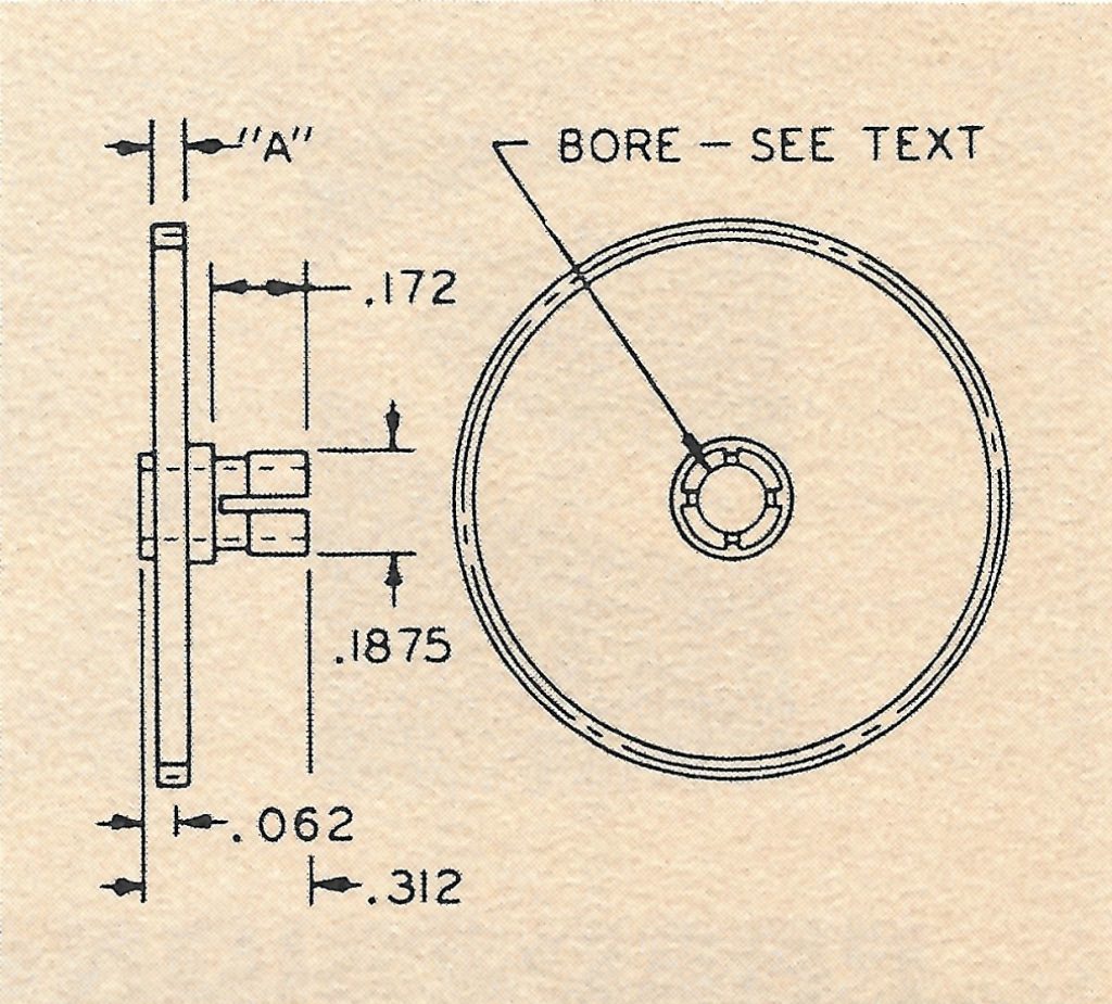
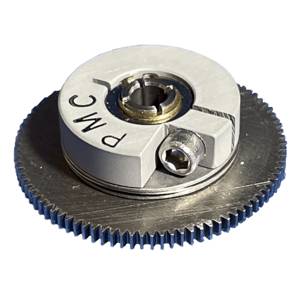
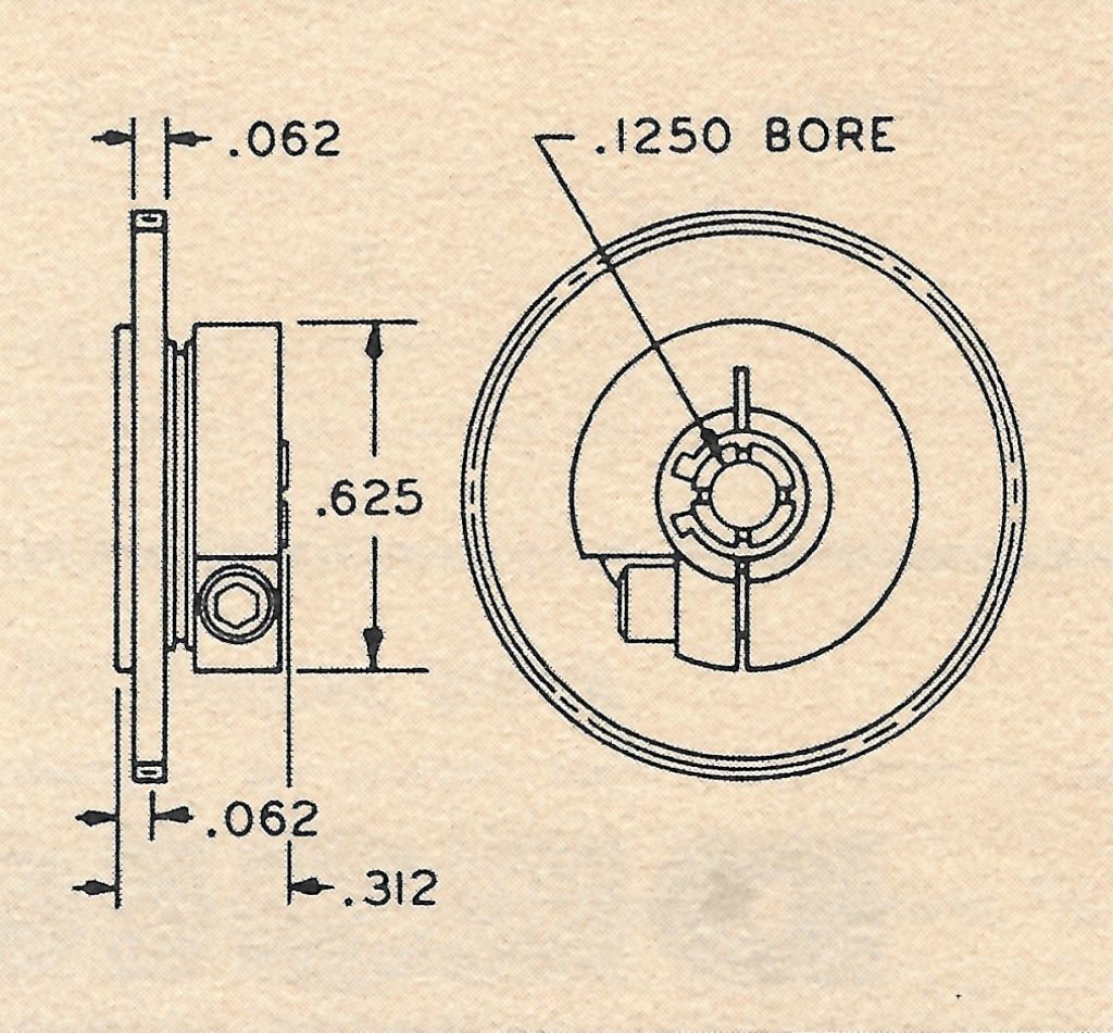
Slip Clutches
Part No.2031
Body and gear of 18-8 corrosion resistant steel, clamp of 24 ST anodized aluminum alloy. Interchangeable with .1250 bore Part No. 2016 and No 2030 gears and of the same precision and tolerances. Size range, 66 to 110 teeth. Specify slip torque.
In conjunction with Part No. 2016 pinions, they provide torque overload protection in all 45 ratios from 1:1 to 5:1 For ordering purpose, preferred sizes are 66,88,99 and 110 teeth.
When Ordering, Specify Part No. 2031 – Number of teeth and Torque.
Gear Clamp
Part No. 2009
For use with Part No. 2016 and 2030 gears. Of 24 ST anodized aluminum alloy. The #2-56 hex socket head clamping screw is fitted with a vibration proof “Nylok” insert.
Shafts
Part No. 2013
Of 18-8 corrosion resistant steel. Supplied with #5133-12 Truarc retaining rings.
Available in a variety of standard lengths for the tabulated uses.
When Ordering, Specify Part No. 2013-7 – Specify the “B” dimensions.
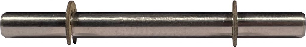
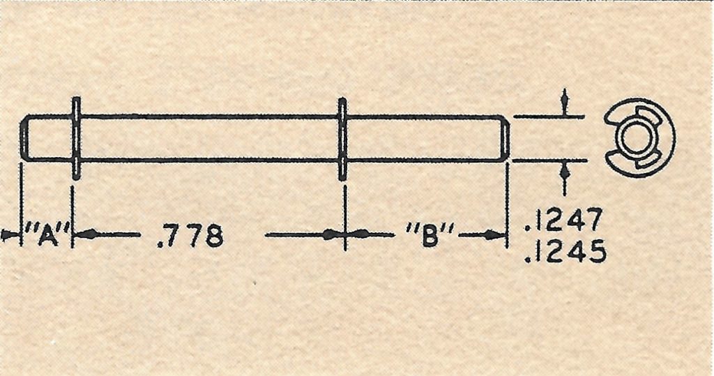
| Part No. | 2013-1 | 2013-2 | 2013-3 | 2013-4 | 2013-5 | 2013-6 | 2013-7 |
| Dim “A” | .141 | .141 | .141 | .312 | .312 | .625 | .500 |
| Dim “B” | .141 | .312 | .625 | .312 | .625 | .625 | As Req. |
| Uses | Internal gearing | One pin coupling extension | One gear extension | Two pin coupling extensions | One pin coupling, one gear extensions | Two gear extensions | Shaft take-off assembly |
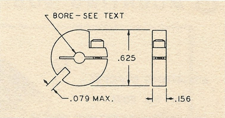
Pin Couplings:
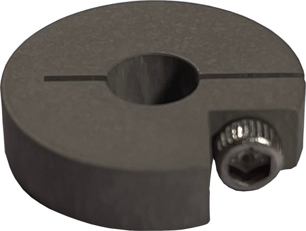
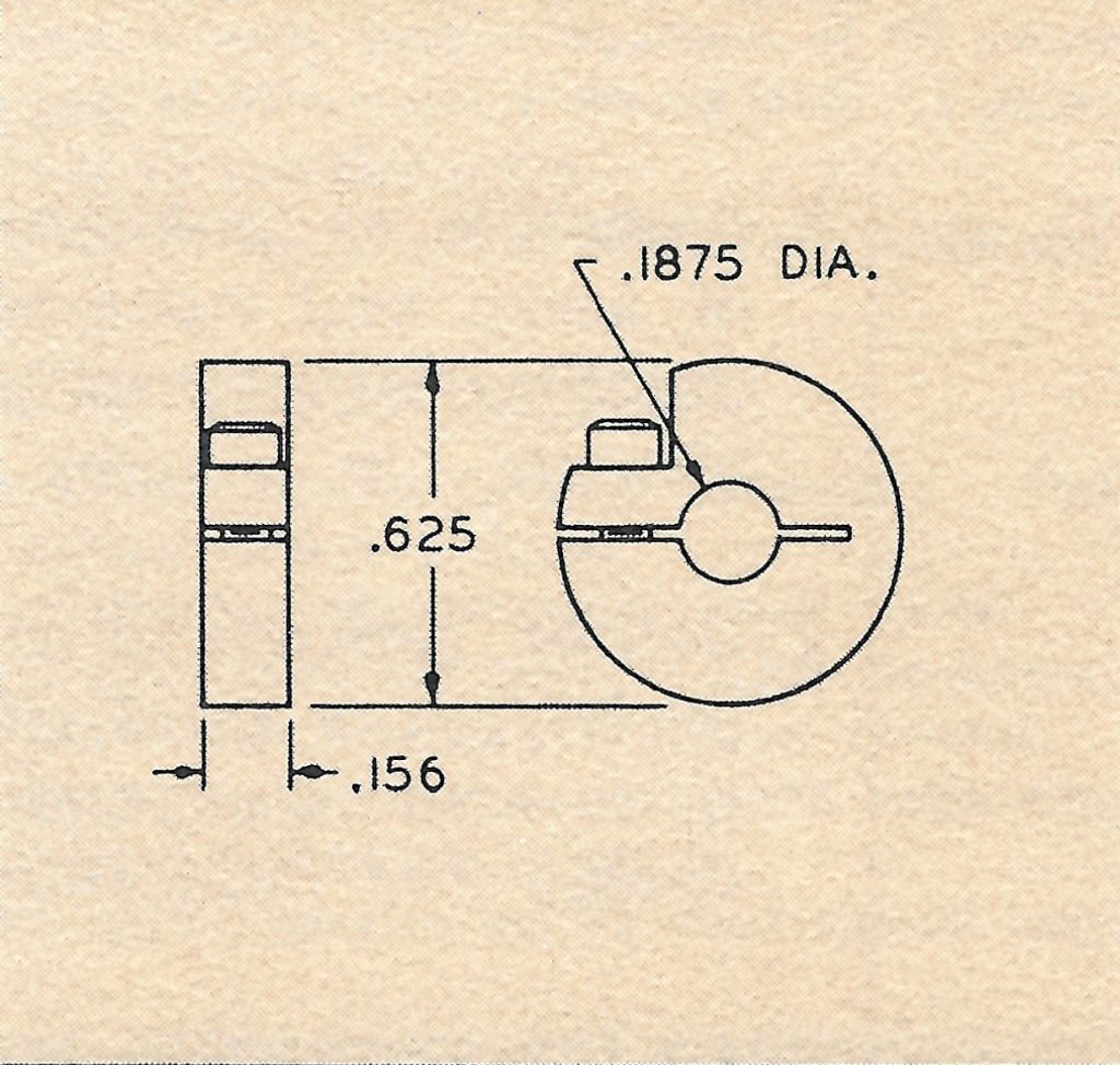
Female: Part No. 2010
For use on the synchro style component shaft. Of 24 ST anodized aluminum alloy. Standard bores are .0900, .1200, and .1250. Bore tolerances are ± .0005. The #2-56 hex socket head clamping screw is fitted with a vibration proof “Nylok” insert.
When ordering, Specify Part No. 2010 – Bore
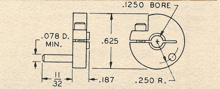
Male: Part No. 2032
For use with Part No. 2013 Shafts. Body of 24 ST anodized aluminum alloy, pin of 18-8 corrosion resistant steel. Bore tolerance ± .0005. The #2-56 hex socket head clamping screw is fitter with a vibration proof “Nylok” insert.
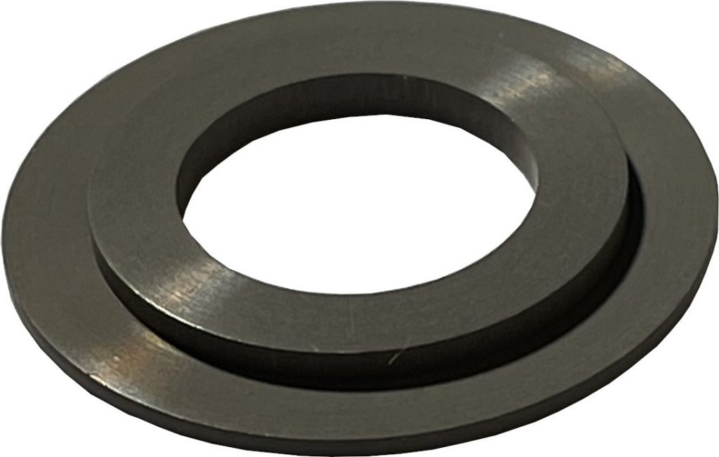
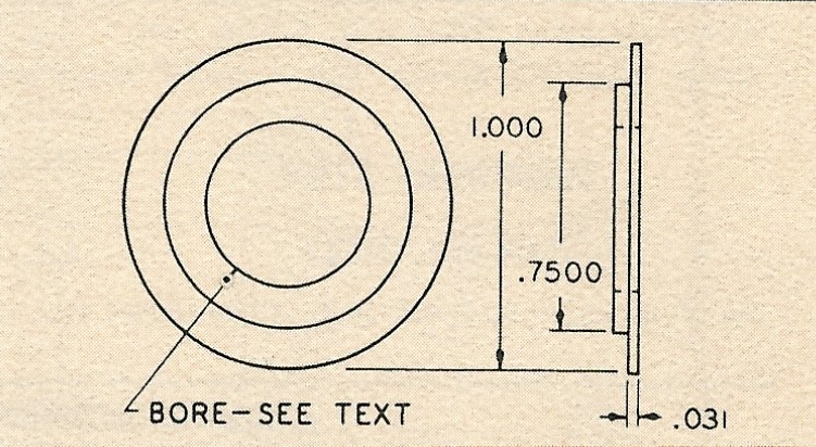
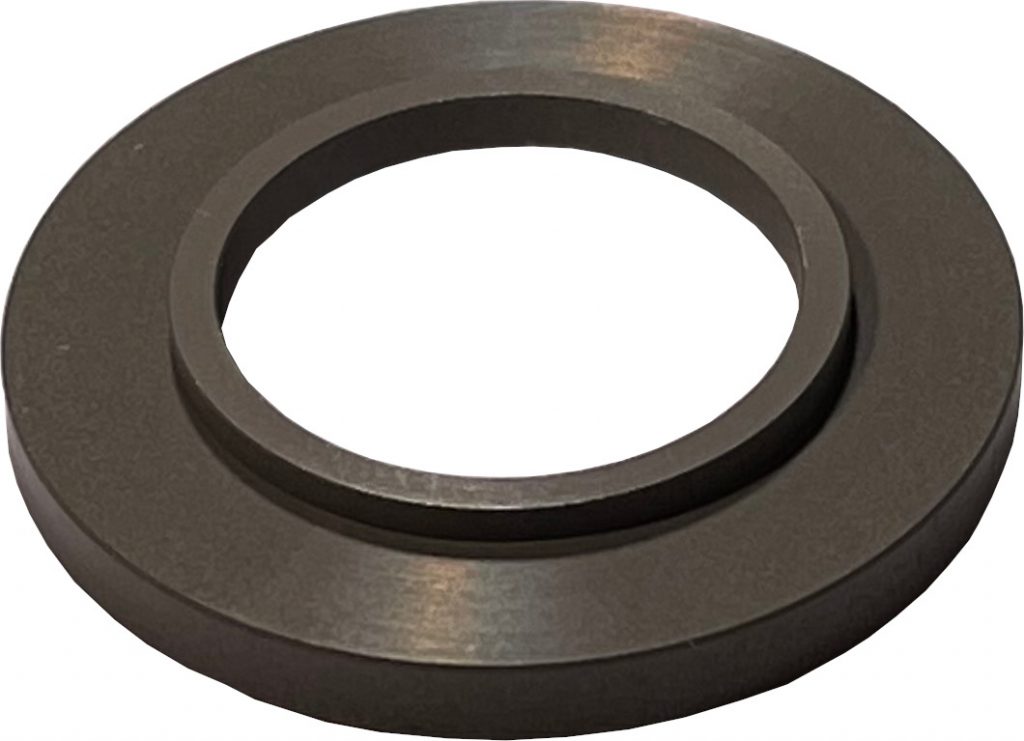
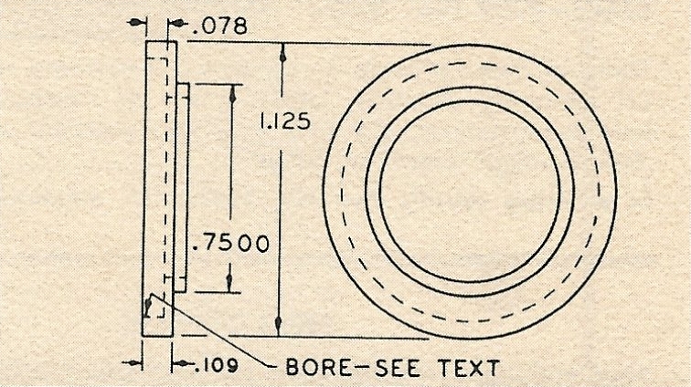
Adapter Rings
Part No. 2017
Adapts all synchro style components with pilot diameters small than .7500 to the .7500 diameter pilot holes of the Part No. 2006 and 2007 Component Mounting Plates.
Standard bores are .5002 and .6252. Bore tolerances + .0005, – .0000. Of 24 ST anodized aluminum alloy.
When ordering, Specify Part No. 2017 – Bore
Part No. 2018
Adapts all synchro style components with pilot diameters larger than .7500 to the .7500 diameter pilot holes of the Part No. 2006 and 2007 Component Mounting Plates. Standard bores are .8127, .8752, .9377 and 1.0002. Bore tolerances ate +.0005, -.0000. Of 24 ST anodized aluminum alloy.
When ordering, Specify Part No. 2018 – Bore
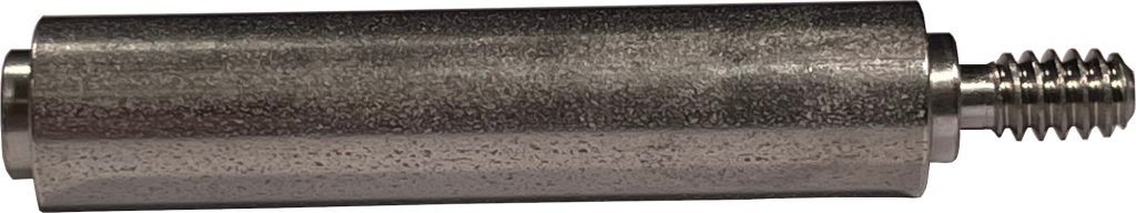
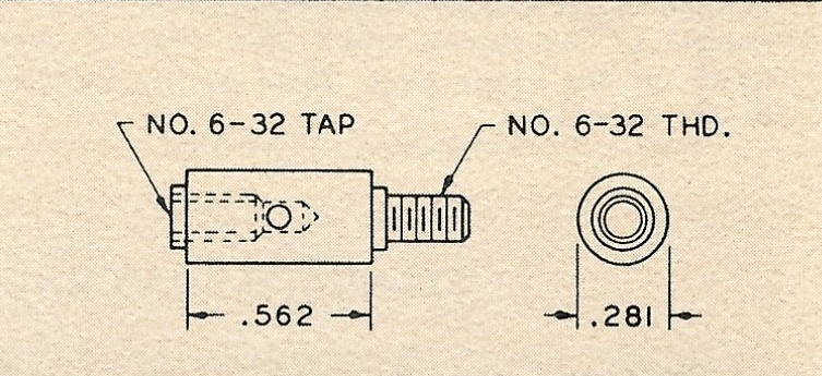
Component Mounting Plate Post
Part No. 2001
Three of these are require to fasten a Component Mounting Plate to a Gear Plate Assembly. Of 18-8 corrosion resistant steel. Has .080 diameter wrenching hole.
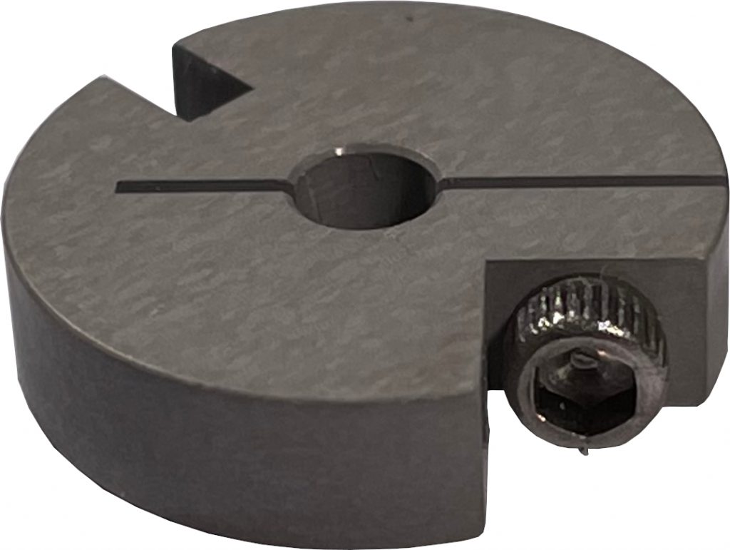
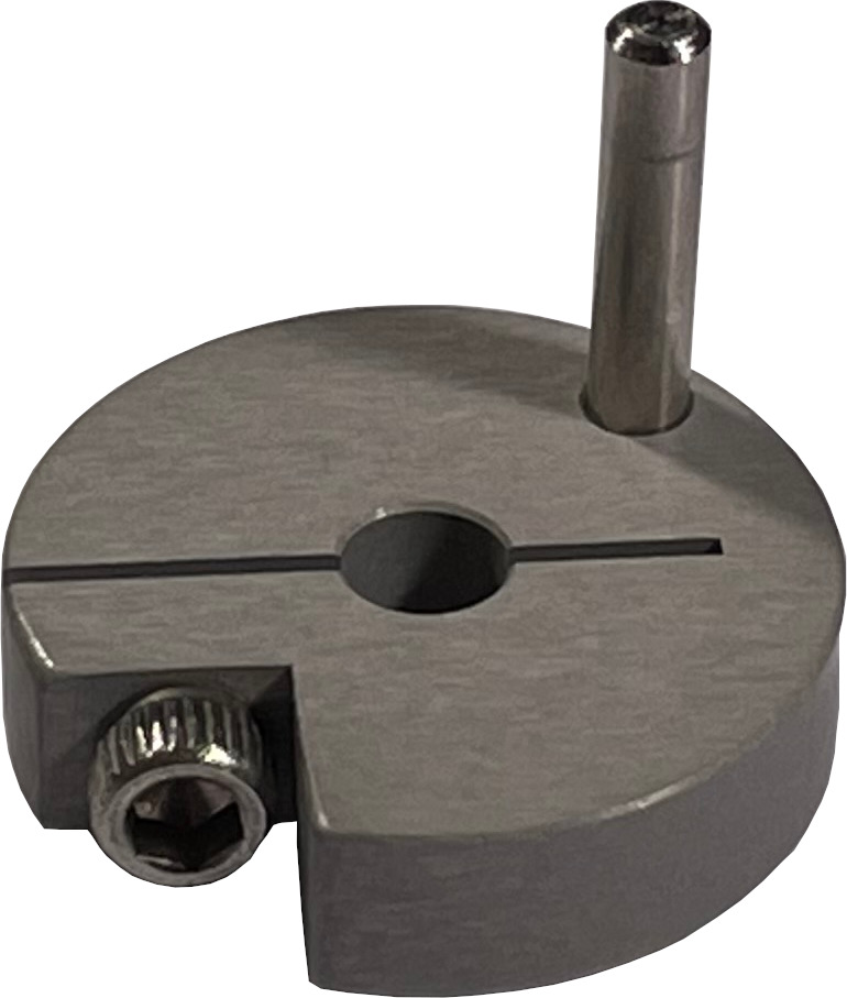
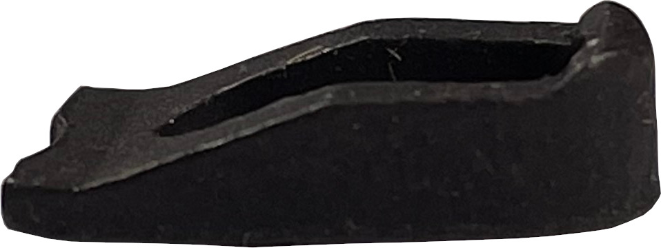
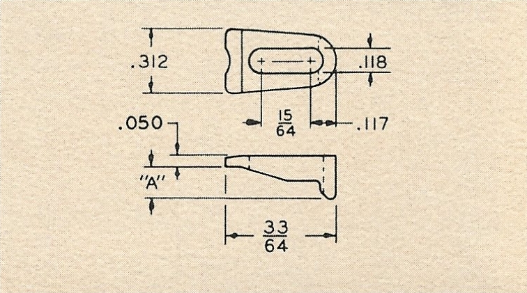
Component Clamps
Part No. 2014
Two are required to clamp a synchro style component. Use Part No. 2014-1 for flanges up to 1/8 inch high, No, 2014-2 for flanges between 1/8 and 3/16 high. Include height of adapter ring when used. Slot permits use of components from 5/8 to 1 1/8 inch in diameter when used with the standard Component Mounting Plates. Of 18-8 corrosion resistant steel, black oxide finish. Part No. 2014-1, Dim. “A” .096; Part No. 2014-2, Dim. “A” .153
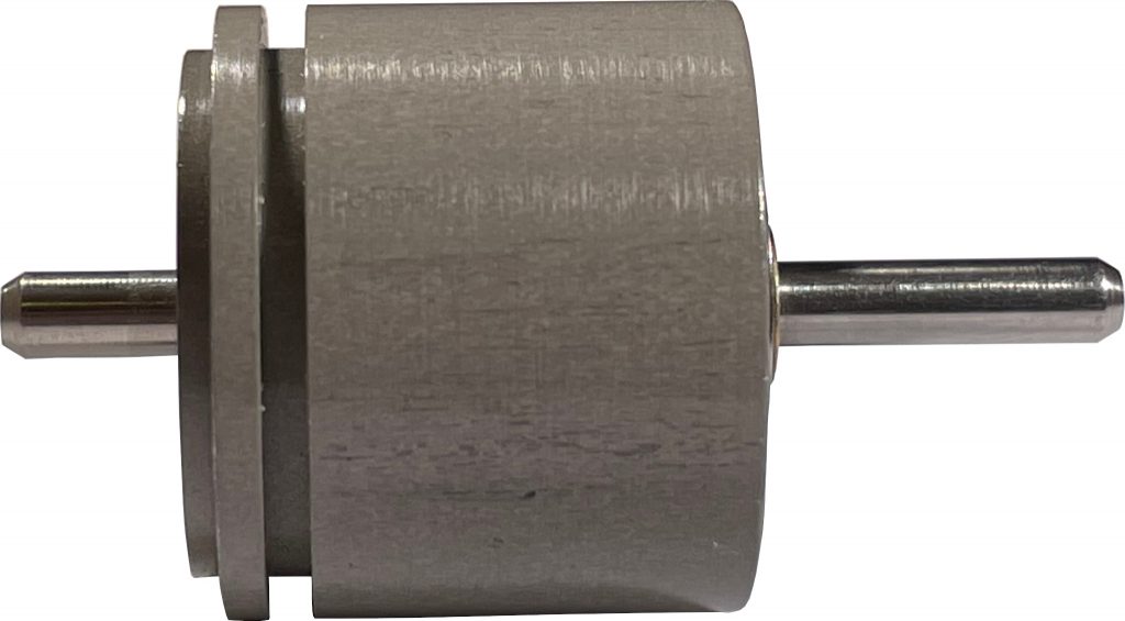
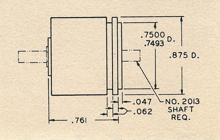
Shaft Take-Off Assembly Part No. 2034
For use in mounting knobs, pointers, dials, cams, and similar components. May be used to gang complete mechanisms.
Consists of two precision double shielded ball bearings in a 24 ST anodized aluminum alloy synchro style housing. Any No. 2013 shaft may be used with this assembly.
*Order Shafts Separately
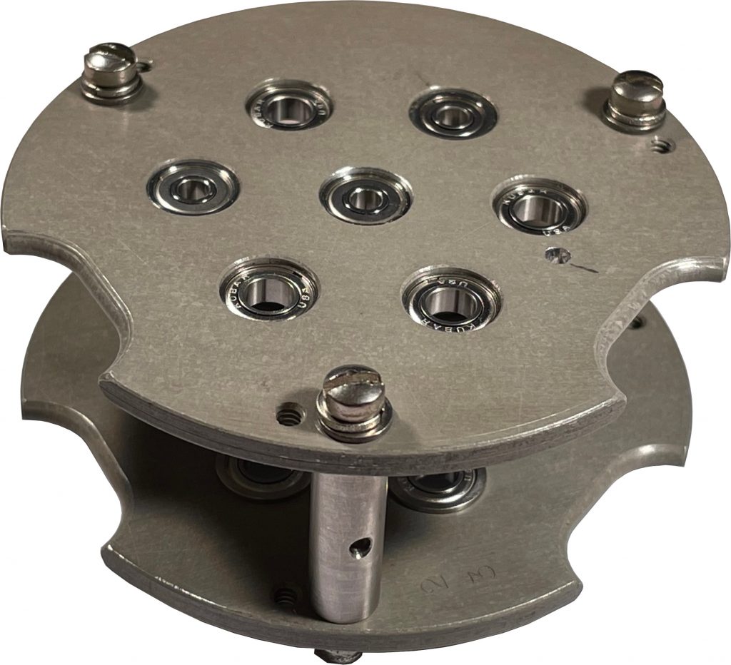
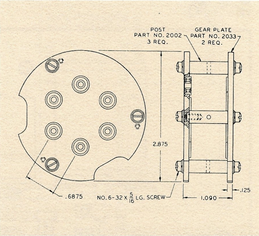
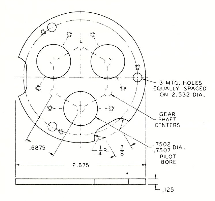
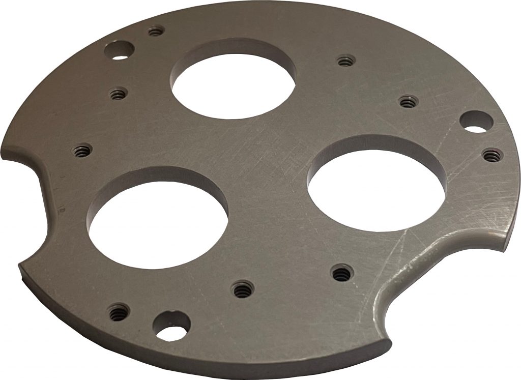
Gear Plate Assembly
Part No. 2036
Basic predesigned mechanism structure. In conjunction with the standard gears and shafts, provides virtually unlimited gearing variations.
Six pairs of precision double shielded ball bearings are provided on .6875 centers for use with Part No. 2013 shafts. Gear plates are 24 ST anodized aluminum alloy, posts are 18-8 corrosion resistant steel. Two wiring grooves spaced at 120° are provided for use in closely fitting enclosures.
While ordering specify Part No. 2036. Individual gear plates and posts may be ordered separately by specifying the part numbers shown in the drawing
Component Mounting Plates
Part No. 2006: In conjunction with Part No. 2036 Gear Plate Assembly, provides 3 pilot holes for mounting rotating shaft components in-line or at .6875 spacing from gear shafts. Tapped holes for Part No. 2014 Component Clamps and 2 wiring grooves spaced at 120° are provided. Mounts all synvhro style components 5/8 to 1 1/8 inches in diameter. Of 24 ST anodized aluminum alloy.
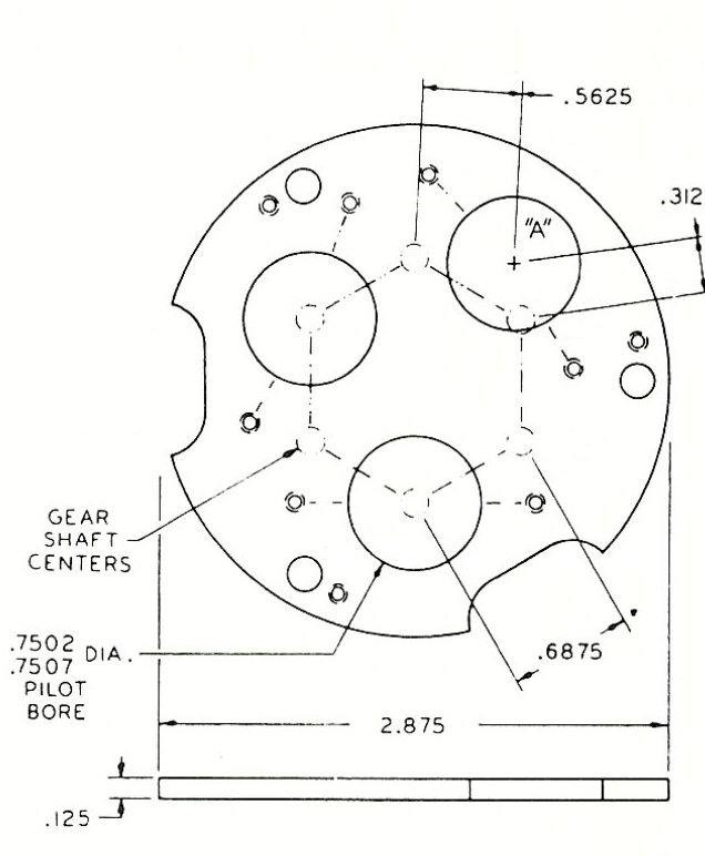
Part No. 2007: Identical with the No. 2006 Component Plate execpt for the location of pilot hole “A” intended for use with integral pinion motors, the .3125 or .5625 centers yield a particularly low inertia first gear pass. A meshing 96 pitch gear pass totals 60 teeth for the .3125 centers and 108 for the .5625 centers.
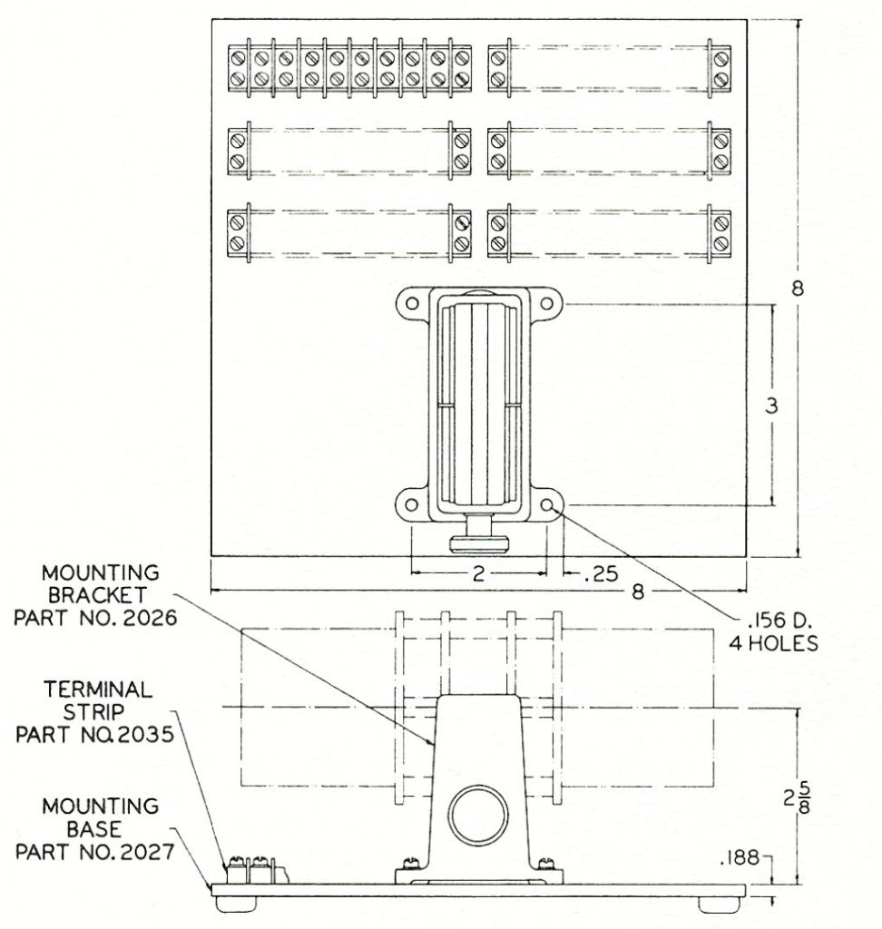
Mounting Equipment
Mounting Bracket
Part No. 2026
For general purpose mechanism mounting. Supports a completed mechanism by clamping the Gear Plate Assembly. Of anodized aluminum alloy
Mounting Base
Part No. 2027
For bread boarding and general test use. Has a capacity of one No 2026 Mounting Bracket and six Part No. 2035 Terminal Strips providing a total of 48 double wiring terminals. Of 24 ST anodized aluminum alloy. Fitted with rubber feet.
Order Mounting Bracket and Terminal Strips separately
Terminal Strip
Part No. 2035
An 8 position terminal strip, Cinch-Jones No. 8-140 or equivalent.
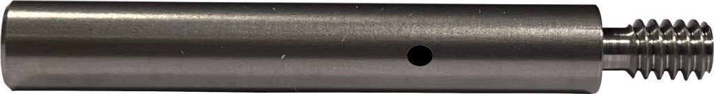
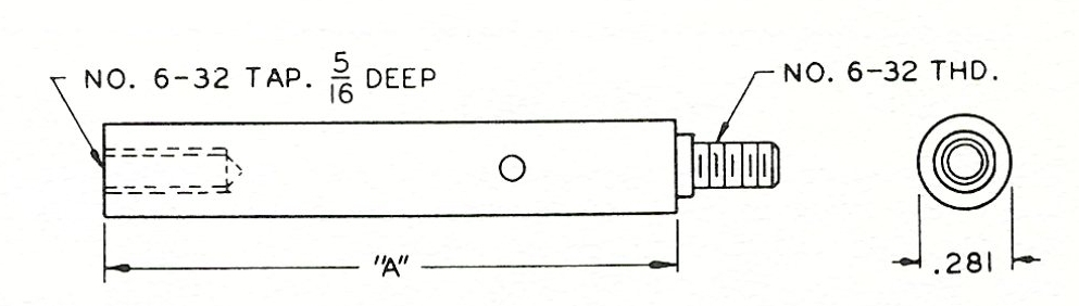
Legs
Part No. 2028
Three of these provide a completed mechanism with a tapped standoff mounting structure. Use in place of Component Mounting Plated hold-down screws. Of 18-8 corrosion resistant steel. Provided with .080 diameter wrenching holes.
When Ordering specify Part No. 2028 – “A” dimensions
Enclosures
Your individual requirements for mechanism enclosures can be fulfilled by Precision Mechanisms Corp. Three inch diameter modules can be supplied with plug-in or AN connectors.
Technical Data
- Standard component capacity, all synchro style units from 5/8 to 1 1/8 inches in diameter
- Maximum component shaft length, 1/2 inch when pin coupled 11/16 inch when geared
- Maximum pin coupling backlash, 15 minutes.
- Solid gear backlash varies linearly from a maximum of 10 minutes at the 110 teeth 5:1 ratio gear to 15 minutes at the 66 teeth 1:1 gear.
- Zero backlash available in all standard ratios.
- Gear pairs printed in color in the Standard Gear Ratio table are preferred for ordering purposes.
Special Requirements
Your special requirements will receive prompt attention. Typical variations from the standard design include:
- Component mounting plates for non-miniature components
- Component mounting plates bored for specific pilot diameters.
- Gear plate assemblies with shaft positions added or omitted.
- Gears, anti-backlash gears, and slip clutches with solid hubs-tapped for set screws and partially frilled for pinning.
- Anti-backlash gears with spring tension set to meet special requirements
- Slip clutches set to slip in accordance with special requirements.
- Materials in accordance with your requirements.
Additional Stocked Gears
| Teeth | Pitch | Ratio | Centers |
| 22 | 80 | 4.00 | .6875 |
| 88 | 80 | 4.00 | 6875 |
| 50 * | 96 | 5.00 | .3125 |
| 62 ٣ | 120 | 4.77 | .3125 |
| 93 § | 96 | 6.20 | .5625 |
| 98 * | 96 | 9.80 | .5625 |
| 122 ٣ | 120 | 9.38 | .5625 |
* Meshes with 10 teeth motor pinion
٣ Meshes with 13 teeth motor pinion
§ Meshes with 15 teeth motor pinion
Standard Gear Ratios
| Pinion | Gear | Ratio |
|---|---|---|
| 22 | 110 | 5.00 |
| 23 | 109 | 4.74 |
| 24 | 108 | 4.50 |
| 25 | 107 | 4.28 |
| 26 | 106 | 4.08 |
| 27 | 105 | 3.89 |
| 28 | 104 | 3.71 |
| 29 | 103 | 3.55 |
| 30 | 102 | 3.40 |
| 31 | 101 | 3.26 |
| 32 | 100 | 3.13 |
| 33 | 99 | 3.00 |
| 34 | 98 | 2.88 |
| 35 | 97 | 2.77 |
| 36 | 96 | 2.67 |
| Pinion | Gear | Ratio |
|---|---|---|
| 37 | 95 | 2.57 |
| 38 | 94 | 2.47 |
| 39 | 93 | 2.38 |
| 40 | 92 | 2.30 |
| 41 | 91 | 2.22 |
| 42 | 90 | 2.14 |
| 43 | 89 | 2.07 |
| 44 | 88 | 2.00 |
| 45 | 87 | 1.93 |
| 46 | 86 | 1.87 |
| 47 | 85 | 1.81 |
| 48 | 84 | 1.75 |
| 49 | 83 | 1.69 |
| 50 | 82 | 1.64 |
| 51 | 81 | 1.59 |
| Pinion | Gear | Ratio |
|---|---|---|
| 52 | 80 | 1.54 |
| 53 | 79 | 1.49 |
| 54 | 78 | 1.44 |
| 55 | 77 | 1.40 |
| 56 | 76 | 1.36 |
| 57 | 75 | 1.32 |
| 58 | 74 | 1.28 |
| 59 | 73 | 1.24 |
| 60 | 72 | 1.20 |
| 61 | 71 | 1.16 |
| 62 | 70 | 1.13 |
| 63 | 69 | 1.10 |
| 64 | 68 | 1.06 |
| 65 | 67 | 1.03 |
| 66 | 66 | 1.00 |
Specifications and Price are subject to change without notice.